Classes for reading a macrogrid file in the dune macrogrid format (dgf)
More...
Classes for reading a macrogrid file in the dune macrogrid format (dgf)
General
The DGF format allows the simple description of macrogrids, which can be used to construct Dune grids independent of the underlying implementation. Due to the generality of the approach only a subset of the description language for each grid implementation is available through this interface.
Usage
We assume in the following that the type GridType is suitably defined, denoting a dune grid type in dimworld space dimension. A point in dimworld space is called a vector.
In general dgf files consists of one or more blocks, each starting with a keyword and ending with a line starting with a # symbol. In a block each full line is parsed from the beginning up to the first occupance of a % symbol, which can be used to include comments. Trailing whitespaces are ignored during line parsing. Also the parsing is not case sensitive.
Some example files are given below (Examples).
First line
Work in progress
- There should be a mechanism to fix the desired refinement edge for simplex grids. An automatic selection is performed using the longest edge, but it should be possible to turn off this automatic selection.
- A callback to the user between parsing the DGF file and the construction of the dune grid; here e.g. a post-processing of the vertex coordinates could be included.
Examples
In two space dimensions:
In three space dimensions:
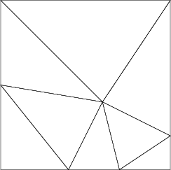
Manual Grid Construction
A tessellation of the unit square into six simplex entities. Some boundary segments on the lower and right boundary are given their own id the remaining are given a default id.
DGF
Vertex % the verticies of the grid
-1 -1 % vertex 0
-0.2 -1 % vertex 1
1 -1 % vertex 2
1 -0.6 % vertex 3
1 1 % vertex 4
-1 1 % vertex 5
0.2 -0.2 % vertex 6
#
SIMPLEX % a simplex grid
0 1 5 % triangle 0, verticies 0,1,5
1 3 6 % triangle 1
1 2 3 % triangle 2
6 3 4 % triangle 3
6 4 5 % triangle 4
6 5 1 % triangle 5
#
BOUNDARYSEGMENTS
2 1 2 % between vertex 1,2 use id 2
2 2 3 % between vertex 2,3 use id 2
4 3 4 % between vertex 3,4 use id 4
#
BOUNDARYDOMAIN
default 1 % all other boundary segments have id 1
#
# examplegrid1s.dgf
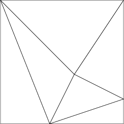
The resulting grid
A tessellation into cubes using the same vertices as before,
DGF
Vertex % the verticies of the grid
-1 -1 % vertex 0
-0.2 -1 % vertex 1
1 -1 % vertex 2
1 -0.6 % vertex 3
1 1 % vertex 4
-1 1 % vertex 5
0.2 -0.2 % vertex 6
#
CUBE % a cube grid
0 1 5 6 % cube 0, verticies 0,1,5,6
1 2 6 3 % cube 1
6 3 5 4 % cube 2
#
BOUNDARYSEGMENTS
2 1 2 % between vertex 1,2 use id 2
2 2 3 % between vertex 2,3 use id 2
4 3 4 % between vertex 3,4 use id 4
#
BOUNDARYDOMAIN
default 1 % all other boundary segments have id 1
#
# examplegrid1c.dgf
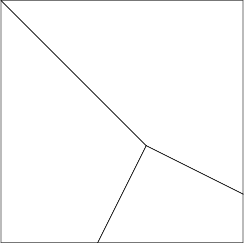
The resulting grid
Using the last input file with a simplex grid or by adding an empty Simplex block
leads to the following macro triangulation
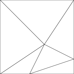
The resulting grid
Automated Grid Construction
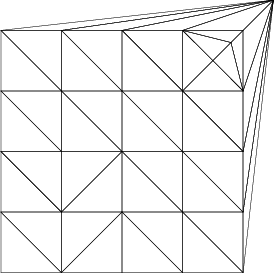
Automatic tessellation using Triangle, with vertices defined as in the example Manual Grid Construction :
DGF
Simplexgenerator
min-angle 30
display 0
% to use Triangle from a certain path, uncomment this path line
%path $HOME/bin % path to Triangle
#
Vertex % the verticies of the grid
-1 -1 % vertex 0
-0.2 -1 % vertex 1
1 -1 % vertex 2
1 -0.6 % vertex 3
1 1 % vertex 4
-1 1 % vertex 5
0.2 -0.2 % vertex 6
#
BOUNDARYDOMAIN
default 1 % all other boundary segments have id 1
#
# examplegrid1gen.dgf
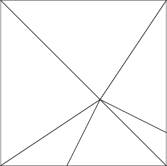
The resulting grid
The quality of the grid can be enhanced by adding the line
in the Simplexgenerator block
The resulting grid
Automatic tessellation using Triangle, with vertices are defined on a Cartesian grid with two additional vertices in the top right corner and one vertex outside the unit square.
All boundary are given a default id.
DGF
Interval
-1 -1 % first corner
1 1 % second corner
4 4 % 4 cells in x and 4 in y direction
#
Vertex % some additional points
0.75 0.75 % inside the interval
0.9 0.9 % also inside the interval
1.25 1.25 % and one outside of the interval
#
Simplexgenerator
display 0 % show result using Triangle viewer
% to use Triangle from a certain path, uncomment path line
%path $HOME/bin % path to Triangle
#
BOUNDARYDOMAIN
default 1 % all boundaries have id 1
#BOUNDARYDOMAIN
# examplegrid2a.dgf
The resulting grid
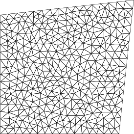
Adding some quality enhancement. The boundaries are numbered counterclockwise starting at the left boundary from one to four.
DGF
Interval
-1 -1 % first corner
1 1 % second corner
4 4 % 4 cells in x and 4 in y direction
#
Vertex % some additional points
0.75 0.75 % inside the interval
0.9 0.9 % also inside the interval
1.25 1.25 % and one outside of the interval
#
Simplexgenerator
min-angle 30 % quality enhancment
display 0 % show result using Triangle viewer
% area restriction
% to use Triangle from a certain path, uncomment this path line
%path $HOME/bin % path to Triangle
#
BOUNDARYDOMAIN
1 1 -1 1.25 1.25 % right boundary has id 1
2 -1 1 1.25 1.25 % upper boundary has id 2
3 -1 -1 -1 1 % left boundary has id 3
4 -1 -1 1 -1 % lower boundary has id 4
#BOUNDARYDOMAIN
# examplegrid2b.dgf
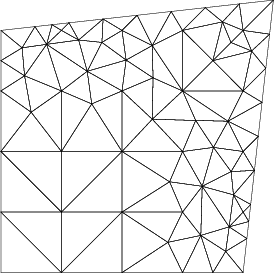
The resulting grid
Using both quality enhancement and a maximum area restriction. The bottom boundary is given the id 1 all other boundaries have id 2; here we do not use a default value.
DGF
Interval
-1 -1 % first corner
1 1 % second corner
4 4 % 4 cells in x and 4 in y direction
#
Vertex % some additional points
0.75 0.75 % inside the interval
0.9 0.9 % also inside the interval
1.25 1.25 % and one outside of the interval
#
Simplexgenerator
min-angle 30 % quality enhancment
max-area 0.01 % area restriction
display 0 % show result using Triangle viewer
% to use Triangle from a certain path, uncomment this path line
%path $HOME/bin % path to Triangle
#
BOUNDARYDOMAIN
1 -1 -1 1 -1 % lower boundary has id 1
2 -10 -10 10 10 % all others have id 2 (could use default keyword...)
#BOUNDARYDOMAIN
# examplegrid2c.dgf
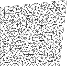
The resulting grid
A similar grid is generated by prescribing the boundary of the domain:
DGF
Vertex % some additional points
-1 -1
1 -1
1 1
-1 1
0.75 0.75 % inside the interval
0.9 0.9 % also inside the interval
1.25 1.25 % and one outside of the interval
#
Simplexgenerator
min-angle 30 % quality enhancment
max-area 0.01 % area restriction
display 0 % show result using Triangle viewer
% to use Triangle from a certain path, uncomment this path line
%path $HOME/bin % path to Triangle
#
BOUNDARYSEGMENTS
1 0 1
2 1 6 3 0
#
# examplegrid2d.dgf
The resulting grid
Using Parameters
We use the same domain as in the previous example but include vertex and element parameters:
DGF
vertex
parameters 2
-1 -1 0 -1
1 -1 1 1
1 1 2 1
-1 1 1 -1
0.75 0.75 2 0.75
0.90000000000000002 0.90000000000000002 2 0.90000000000000002
1.25 1.25 -1 1.25
#
simplex
parameters 1
0 4 3 1
4 0 1 -1
3 4 5 1
5 1 2 1
1 5 4 -1
2 6 3 1
6 2 1 -1
5 2 3 -1
#
boundarydomain
default 1
#
Simplexgenerator
min-angle 30 % quality enhancment
max-area 0.01 % area restriction
display 0 % show result using Triangle viewer
% to use Triangle from a certain path, uncomment this path line
% path $HOME/bin % path to Triangle
#
# examplegrid2e.dgf
The results in piecewise constant data on the elements and piecewise linear date using the vertex parameters:
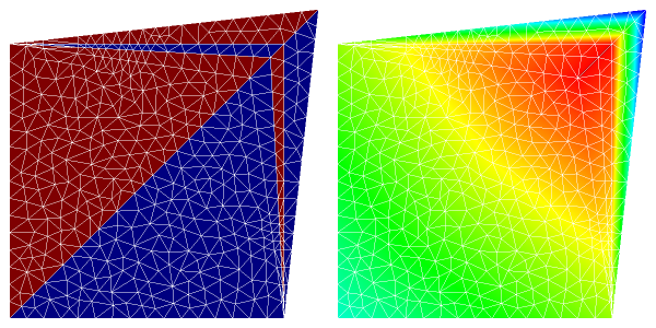
The resulting grid with element and vertex parameters
Interval Domain
A automatic tessellation of the unit square using a Cartesian Grid. All boundaries have id 1.
DGF
Interval
0 0 % first corner
1 1 % second corner
4 8 % 4 cells in x and 8 in y direction
#
Simplex
#
GridParameter
% set overlap to 1
overlap 1
% set closure to none for UGGrid
closure none
% generate copies in UGGrid
copies yes
% set heap size for UGGrid
heapsize 1000
#
PERIODICFACETRANSFORMATION
% set periodic boundaries in x direction
% 1 0, 0 1 + 1 0
#
BOUNDARYDOMAIN
default 1 % default boundary id
#BOUNDARYDOMAIN
# examplegrid5.dgf
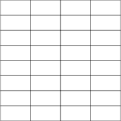
The resulting grid using YaspGrid<2>
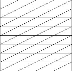
The resulting grid using AlbertaGrid<2,2>
If UGGrid<2,2> is used the result would be the same as for YaspGrid<2>. If an empty Simplex Block
is added than the same simplex grid as for AlbertaGrid<2,2> would be constructed.
 |
Legal Statements / Impressum |
Hosted by TU Dresden & Uni Heidelberg |
generated with Hugo v0.111.3
(Jun 19, 23:17, 2026)
|
Legal Statements / Impressum |
Hosted by TU Dresden & Uni Heidelberg |
generated with Hugo v0.111.3
(Jun 19, 23:17, 2026)